CONNECTING SHAPES
SCD specific connectors
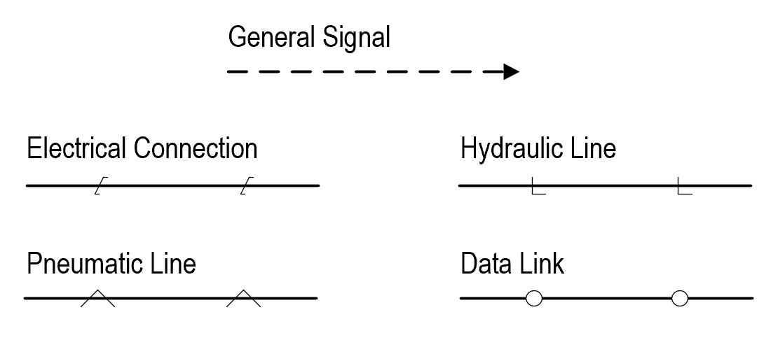
All connectors needed for the SCD are designed as shapes and can be found in SCD Main Shapes side panel
There are multiple types of connectors:
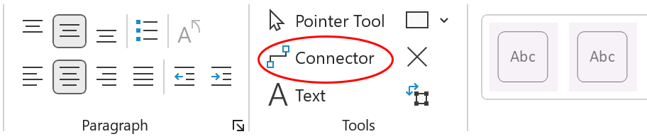
WARNING! Do not use original Connector tool provided by Visio. This can cause inaccuracies in reports.
Connection points
Every shape in Visio has connection points. They are used to connect shapes properly. As you move connector close to the connection point Visio will suggest to glue them together. Glued elements
will remain connected despite their relative positioning.
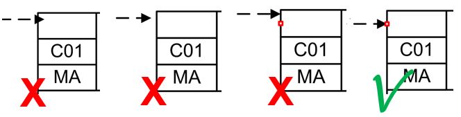
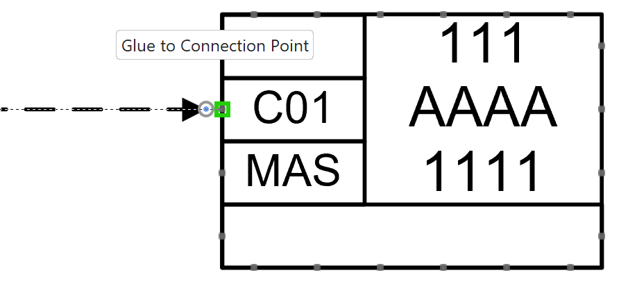 Make sure that all connections are made using shape’s connection points.
Any loose shapes or connectors can cause inaccuracies in reports.
Terminals
When SCD shapes are connected using General Signal, Connection Manager window appears, providing list of possible inputs/outputs for each shape. Contents of the list differ depending on the type of shapes being connected.
E.g.: After incoming signal is connected to SBV function block, Connection Manager displays the list of all possible input terminals for SBV block based on NORSOK.
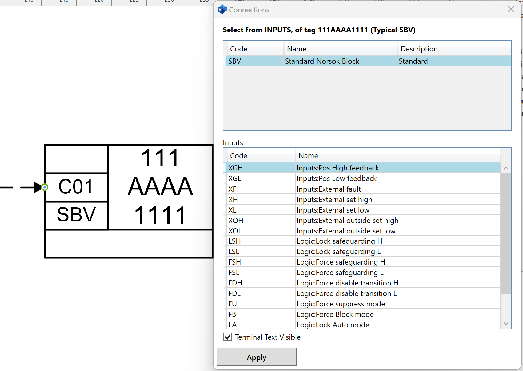 A list of terminals in Connection Manager is automatically filled with terminals available for current type of function block or software function and based on direction of connected signal line.
Terminals that are already in use are shown in gray and are not selectable.
A list of terminals in Connection Manager is automatically filled with terminals available for current type of function block or software function and based on direction of connected signal line.
Terminals that are already in use are shown in gray and are not selectable.
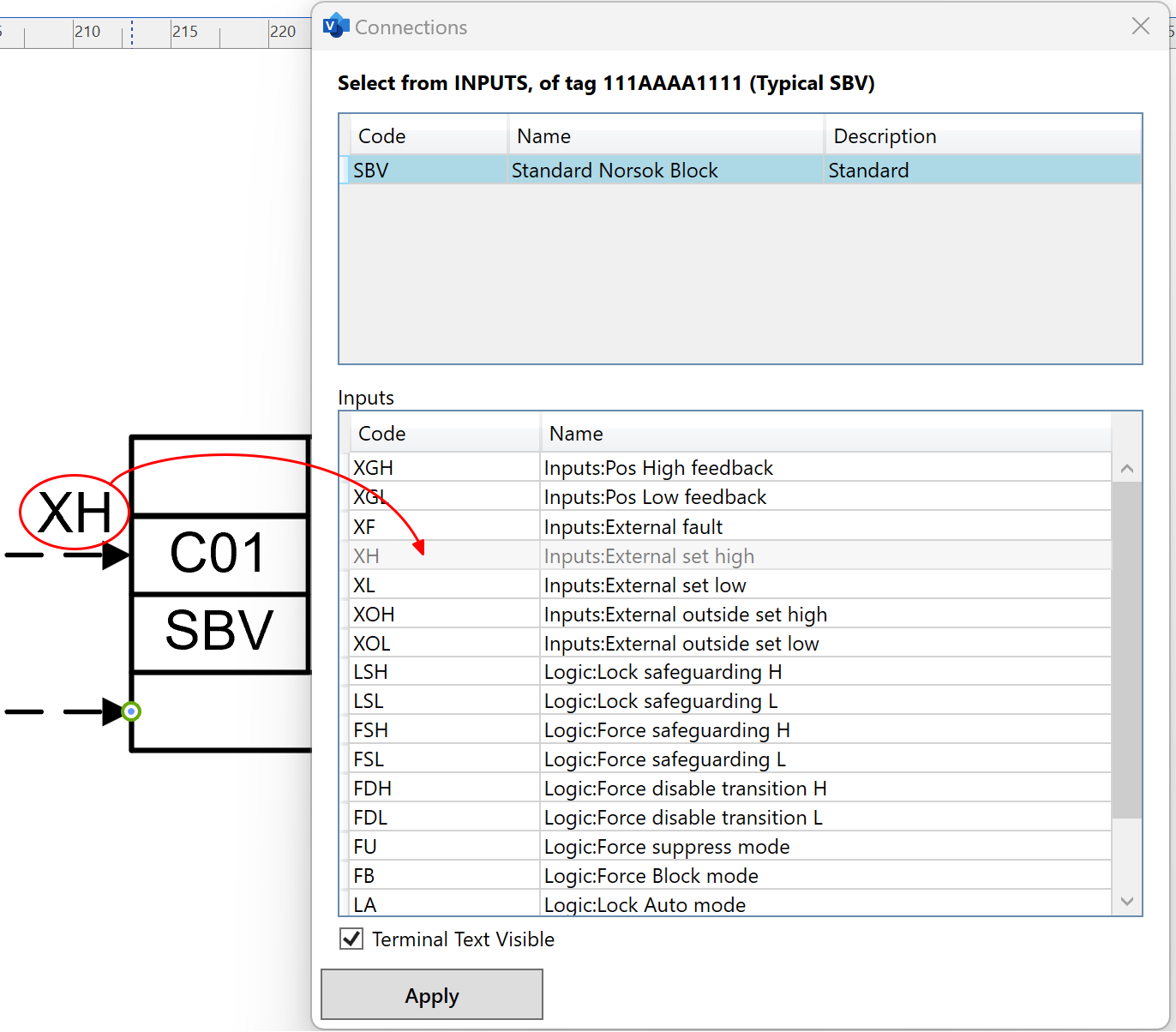
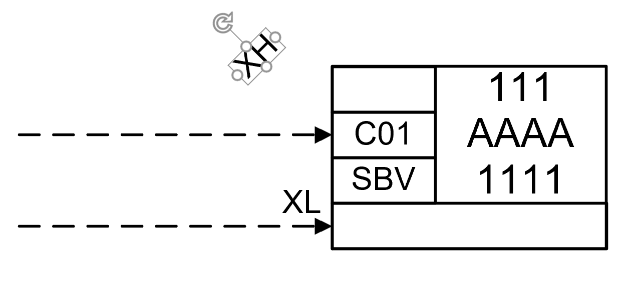
Adjustable Terminals
Once the signal line is connected and the terminal is selected, it's label can be moved and rotated freely. The label will automatically reset it’s position when signal line is disconnected or reconnected to another shape.
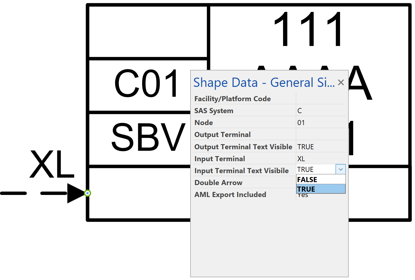
 Label visibility can be changed using Shape Data window.
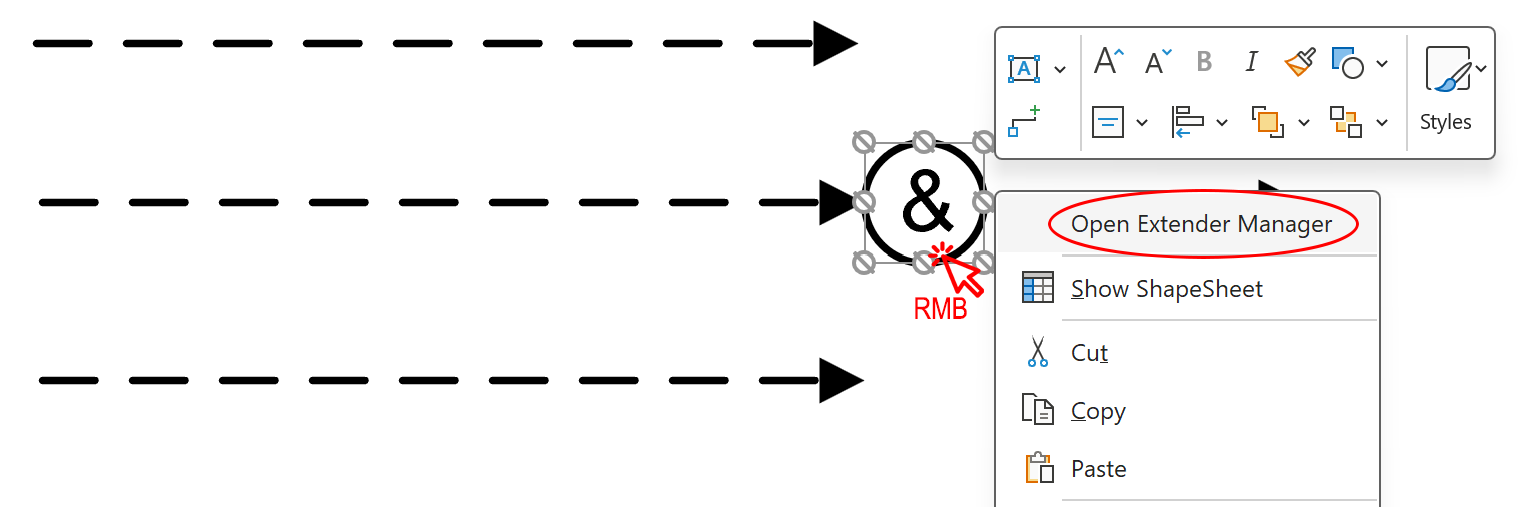
Extender Manager
Additional connection points can be added to Function Blocks or Software Functions using Extender Manager.
- Click right mouse button on Function Block or Software Function, you want to add connection points to.
- Click Open Extender Manager button.
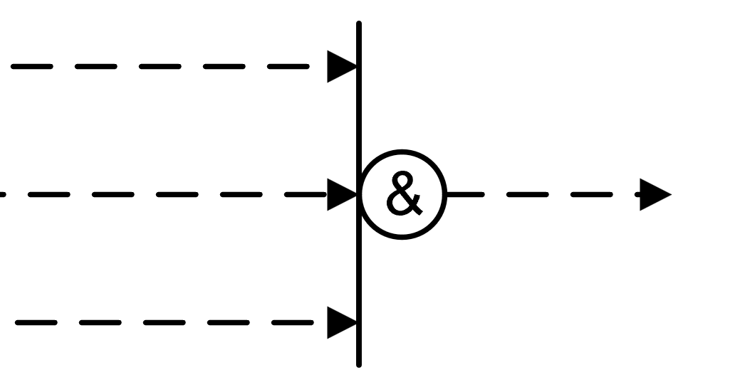
- Click «+» button or input required number of extra connection points from keybord to add them to selected shape. Extender’s length is adjusted automatically to fit extra connection points.
- Use newly added connection points on the extender to connect all signals. Signals connected to the extender have the same properties as signals connected to a Function Block or Software Function directly.